In a mechanical animation, parts have to move together. In the agent-built crank-slider I use here, a rotating wheel drives a rod and sliding block, and the rod should stay attached to the crank pin and the slider pin as the mechanism moves. Checking each object’s reference position does not establish that connection: a rotating arm can keep its origin in the right place while its tip moves away from the part it should drive.
My earlier motion article checked saved world origins and the clock that gives those samples meaning. To examine the connection itself, I added a check to Scene Acceptance, my acceptance harness for reviewing saved 3D deliveries, that measures the distance between two named points on moving objects. I tested it on the delivered assembly and deliberately broken copies.
The check also needs a sampling schedule: the times at which it measures that distance. Comparing schedules showed that each could miss a separation the other caught, so I want the report to name its measured times and leave continuous attachment of a rotating part as an open question.
For an animation explaining how the mechanism works, a connection that separates can misrepresent how one part drives another. A still view may never reveal it. If the motion is later used to inspect the space the mechanism moves through, an incorrect path could also affect that inspection. The distance check here measures attachment at selected times; it does not assess collisions or simulated forces.
Measure the connection the task depends on
The new contract, the file of targets and tolerances the check reads, names a point in each object’s local coordinates, the interval to inspect and the largest permitted gap. At each selected time, the checker transforms both points into world coordinates, converts stage units, the saved scene’s length units, into metres and measures their separation.
This lets the calling application, the software or agent that receives the delivery, state a requirement such as “the end of this rod must remain within 0.5 mm of that pin at these times.” It does not require the checker to infer mechanical joints from names or appearance.
The transform work comes from OpenUSD’s UsdGeomXformCache; OpenUSD is the library behind the USD scene format the harness reads. It includes the parent transforms affecting each point. The check supplies the task-specific comparison and records the sampled positions, distances and times.
The local points matter. An origin is often placed at a convenient construction reference rather than the contact the application cares about. For the assembly’s rod, the two useful local points are its ends, at (0, 0, 0) and (0.110, 0, 0) in the delivered stage’s metre units. Those are compared with the crank and slider pin origins.
A small angle change with a large interior error
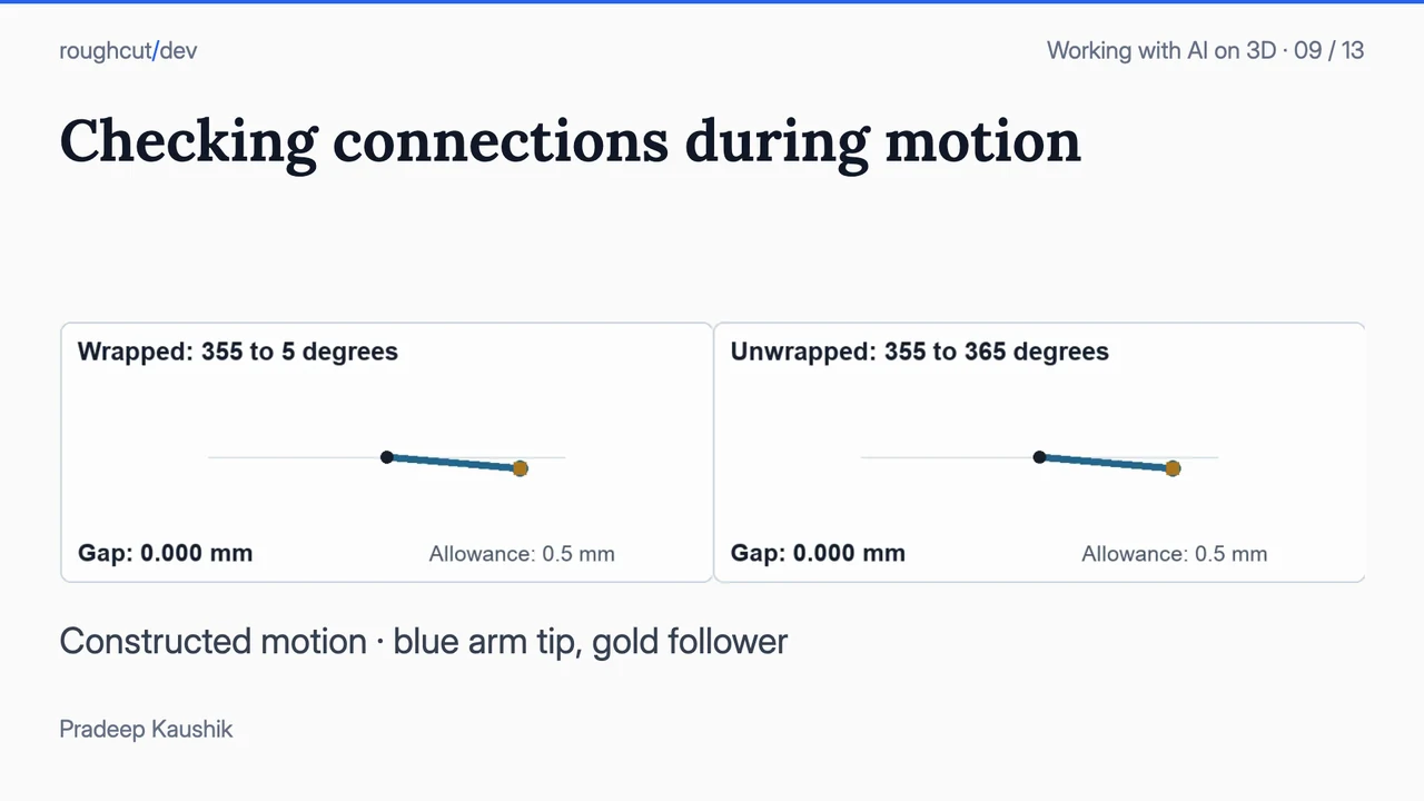
Before applying the check to the assembly, I used a smaller constructed scene, a control built so the geometry is easy to calculate. A 35 mm arm begins at 355 degrees and ends at the same orientation represented by 5 degrees. A follower, standing in for the part the arm drives, moves between the corresponding positions of the arm’s pin, the point at its tip.
There are two ways to author that angular transition. The unwrapped version goes from 355 to 365 degrees. The wrapped scalar version goes from 355 to 5. Both have the same endpoint poses, but linear interpolation of those scalar values takes very different routes through the interval.
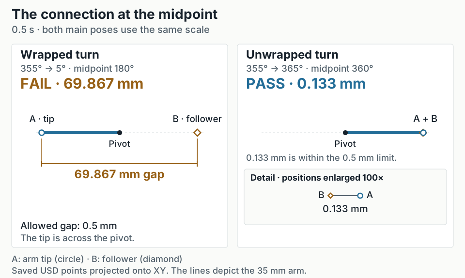
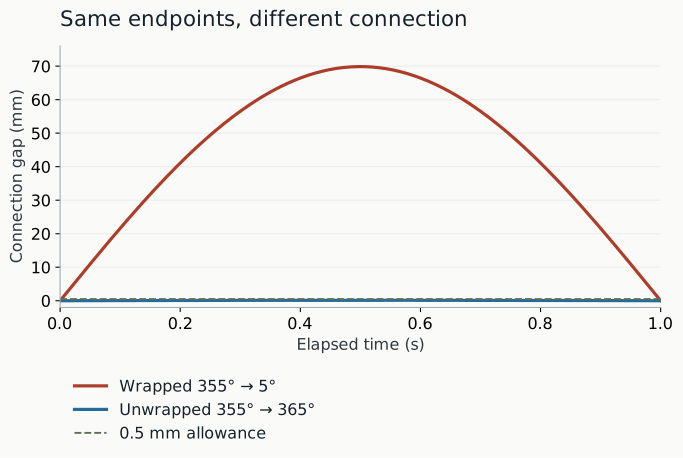
At the midpoint, the wrapped arm is at 180 degrees. Its pin is on the opposite side of the pivot from the follower. The measured gap is 69.867 mm. The unwrapped arm reaches 360 degrees and its measured gap is 0.133 mm, within the 0.5 mm allowance.
XY projections of points read from the saved USD controls at 0.5 seconds. The lines depict the 35 mm arm; these are diagrams of the measured positions. Both main views use the same scale. The unwrapped detail enlarges positions 100× so its small gap remains visible.
That small remaining gap is expected in this fixture: the follower interpolates along the chord between its endpoints while the arm tip follows an arc. Keeping it visible is more informative than constructing a passing control with zero error by definition.
Watch the two saved motions between their matching endpointsHide the connection replayOne second of saved USD motion, slowed five times with holds at the start, midpoint and end. Blue marks the arm pin; gold marks the follower. Both projections use the same scale. These are the constructed controls above, replayed from their saved transforms without contact simulation.
The coding assistant built the test fixtures, evaluator and replays under my direction, using OpenUSD 25.11. The original controls are in the companion download described below.
The assistant checked the midpoint numbers with a separate trigonometric expression. For radius r = 35 mm and an endpoint offset of 5 degrees, the gaps are r × (1 − cos(5°)) and r × (1 + cos(5°)). The expressions agree with the USD read-back to far below a micrometre in this run. The same assistant wrote both, so this confirms the arithmetic by a second route and nothing more.
The origin-only baseline, the saved-origin check from the motion article, accepts both scenes. Checking only the connection at the endpoints also accepts both. Measuring the right relationship at the midpoint separates them.
Dense diagnostic samples of the saved USD controls. The threshold applies to the connection gap. A stationary arm origin would not reveal this separation.
Other controls preserve the 35 mm arm’s result when stage distances are expressed in millimetres, exercise moving parent transforms, and request times beyond the authored duration. Missing clock metadata and uncovered intervals return insufficient evidence, the harness result for a requirement the supplied files cannot settle. The evaluator does not fill those gaps with a default timing assumption.
A schedule can improve coverage and still miss motion
Uniform samples, here one every quarter second, are simple to explain and reproduce. I compared that baseline with a schedule that also collects authored transform-key times affecting the two points, including their ancestors in the scene hierarchy, and adds a midpoint between each adjacent time in that combined set.
The difference appears in a brief excursion authored around 0.12 seconds. Quarter-second samples see the connection before and after it has moved away. They pass. The key-aware schedule includes the excursion and measures a gap of 49.497 mm, so it rejects the scene.
The key-aware schedule isn’t better in general. Here is a scene where it loses: the arm makes two full turns between its start and end keys while the follower stays fixed at the starting pin position. The arm aligns with the follower at the endpoints and midpoint, so a schedule containing only those three times passes. Quarter-second samples find the arm on the opposite side and measure a 70 mm gap.
Scroll sideways for more columns.
Constructed motion
Endpoints only
Quarter-second samples
Keys and interval midpoints
Short unwrapped turn
Pass
Pass
Pass
Wrapped scalar turn
Pass
Fail
Fail
Brief excursion around 0.12 s
Pass
Pass
Fail
Two full turns between keys
Pass
Fail
Pass
The table is why the pack, the reusable group of checks the contract selects, reports its schedule and actual sample times. “Checked between keyframes” is too vague to support an acceptance decision. The two-turn control passes exactly what its three-time contract asks, while contradicting a stronger claim that the connection stays together throughout the interval.
More samples found these cases; they can’t rule out the next one. A real bound needs a rule for how the motion may move between samples, and this pack has none.
Apply it to the delivered assembly
The real application reuses the exact saved USD from the earlier assembly article, together with its delivered HDR dependency, an image file the scene references. No new production attempt was made. The test measures both ends of the connecting rod over the four-second animation, using eight uniform segments plus the relevant transform keys and midpoints.
That produces 481 sample times per connection. The largest measured crank-end gap is 0.003005 mm; the largest slider-end gap is 0.000955 mm. Both are below the existing 0.5 mm threshold.
The first test bundle, the folder of files submitted for checking, omitted the assembly’s HDR file, so the harness returned insufficient evidence before checking the connections. A second bundle contained the same scene and its missing dependency; that complete delivery passed.
For the failing control, I appended a 1 mm local translation to the rod pose in a separate copy. The resulting maximum gaps are about 1.003 mm and 1.001 mm, and the check rejects it. This offset is an injected defect. It was not present in the delivered artifact and should not be counted as an agent failure.
The next brief did not require constant speed
The connection check also ran in a later evaluation, which supplied three more mechanisms. Their brief differed from the assembly’s: a 42 mm crank radius, 140 mm rod, 25-degree starting phase and one counterclockwise turn in three seconds. All three passed the final selected artifact checks. The connection pack evaluated 769 times per connection; the largest recorded gap was about 0.009995 mm against a 0.5 mm allowance. Two separately declared diagnostic grids supplied another finite comparison at 514 times.
This evaluation also tested how the brief had been interpreted, because the analytical reference, the calculated motion the mechanisms were compared with, assumed constant speed even though the assignment left the speed profile open. My evaluating assistant corrected how the brief mapped to checks, so that the uniform-speed comparison became advisory, reported without blocking acceptance, while sampled phase, direction, loop closure and attachment remained required. A deliberately varied-speed copy then passed the required checks despite disagreeing with the advisory trajectory. Wrapped-angle and offset-rod copies failed the connection checks.
That varied-speed copy deserves a place beside the offset rod. One tests whether the evaluator allows a legitimate production choice; the other tests whether it rejects a broken connection. The supplied mechanisms alone did not expose our constant-speed assumption. Requiring a uniform speed the job’s owner never asked for would have made acceptance stricter without telling me anything more about whether the rod stays on its pin.
Try a relationship contract
For the small arm control, the check parameters are:
Elapsed seconds are measured from the authored stage start. Local points use stage units; the gap threshold uses metres. The contract selects motion.connection, version 0.1.0, with check distance. Its full form is included beside every frozen scene. This sampled check shipped in release 0.5; it was not part of v0.3.0.
The v0.1 companion includes eight constructed motion cases, the original assembly bundles, code and reports. The later three-mechanism study is not included. After installing it with the texture follow-up’s setup commands, run:
The matrix keeps origin, endpoint, uniform and dense diagnostic reports alongside the selected schedule. The assembly runner verifies its frozen bundles before and after evaluation.
Later continuous checks and the remaining rotation limit
The development package, an unreleased 0.7 snapshot of the harness, adds two checks that bound the whole interval: a continuous connection check, and mechanical.relationships with attachment, sliding and engagement, for parts that stay joined, slide along an axis or overlap along it. Both admit only piecewise-linear translation with the other transforms held static, and animated rotation comes back unknown, neither passed nor failed. So for a crank and rod like these, the rod ends are still checked at the sampled times, and the two-turn case is still open.
Report the sample times and leave continuous attachment open
I would use the reported sample times to decide whether the check covers the animation’s use, because a pass at named times tells me something definite about those times and nothing about what the authored animation does between them. The three-mechanism brief asked for attachment at any intended animation time, so all three broader assessments stayed NEEDS_REVIEW, the result that withholds acceptance while a required question is open, even though every recorded sample passed.
Disclaimer: The views and opinions expressed in this account are those of my own and do not represent those of my employer, NVIDIA.